I can’t remember where the seed of this project was found, but when it was planted in my 7-year-old daughter’s mind it took root and grew over a number of our daily dog walks. Given we’re now in lockdown and are always looking for interesting and creative things to do at home, the time seemed right to make it happen. Fortunately, I came across this excellent series on YourTube from Explaining Computers which became the template for our Jnr Trak (aka Devastator tank mobile robot platform) project.
When we’d first talked about the idea, I had a picture of Big Trak in my mind. Growing up, I’d always wanted one and eventually got one when I was much too old to really appreciate it. I swapped my Acorn Electron computer for a Big Trak and Sinclair ZX Spectrum (with rubber keys!) when I was in secondary school! I thought it was a great deal, although my Mum didn’t necessarily agree at the time.
So when I saw the video, it was an easy decision. Not only would we be making a cool looking robot, but I’d have some easy to follow along instructions to boot!
At the point I ordered the Devastator kit, the best source was DFRobot. Some of the UK based suppliers were out of stock (and more expensive) and the price on Amazon was just crazy. DFRobot had free shipping over £100, and shipping below that was going to cost almost £25, so I decided to add a Gravity Starter Kit for Arduino which was a little more than the shipping cost, but not much and at the time I thought I might be able to use with the Devastator kit. I’ve still not really played with it in anger, as I couldn’t easily see how I’d use it with this project.
The kit was delivered incredibly quickly from China (it left on a Thursday and was delivered to me on the next Monday!) but also incurred some custom charges, which DHL kindly doubled with their adminitration costs! Even after those, I’d got the Devastator and Gravity Kits in the UK for just over £130, which was less than the Devastator kit was available on Amazon.
In the last 4 weeks since that package arrived, i’ve probably ordered another 10 which has increased the total project cost somewhat but has left me with a nice supply of home electronic components for other things we might do in the future. Other than some screwdrivers to put together the robot and a very old and next-to-useless soldering iron, I had nothing so needed to buy a selection of LEDs, resistors, switches, wires, connectors, batteries, and various other things. I also invested in a new soldering iron, another Pi (which I blogged about here) and some storage boxes to keep everything in!
I’ve not even started on the build, so this blog is probably just going to brush over the surface or it will turn into something akin to War and Peace!
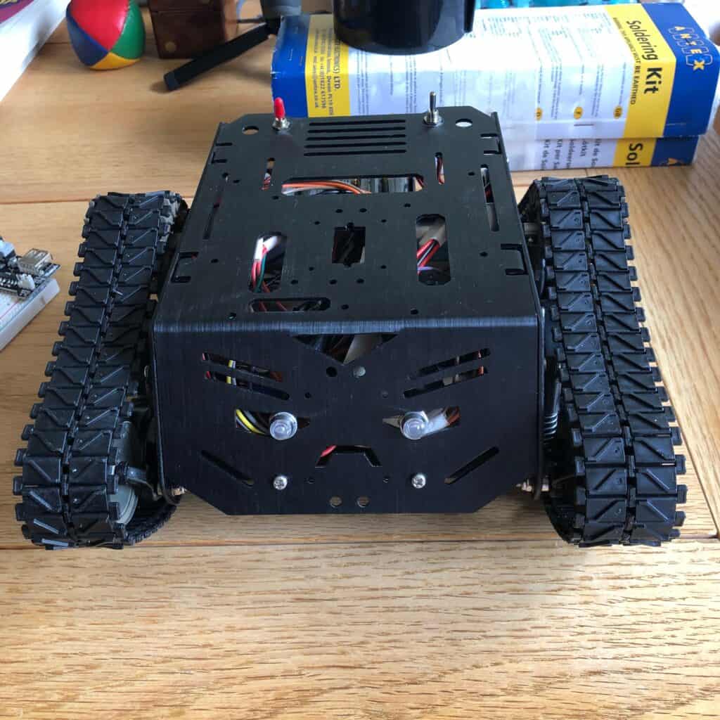
Devastator
Building the actual robot platform was by far the easiest part of the project. Even with my daughters ‘help’, we’d put everything together in a few hour-long sessions. It’s no more complicated than screwing a few parts together and then attaching some nuts and bolts. It’s a pretty sturdy thing, with the main structure and motors of metal construction, and the suspension and wheels made of hard plastic. The tracks needed to be shortened, but again this was well covered at the start of this video, and only took 10-15 minutes to do both tracks.
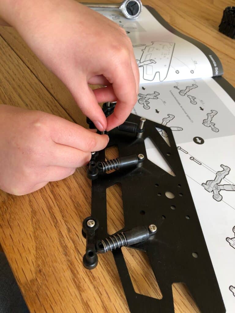
These are a bit fiddly! 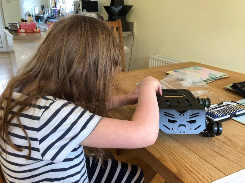
Is this tight enough? 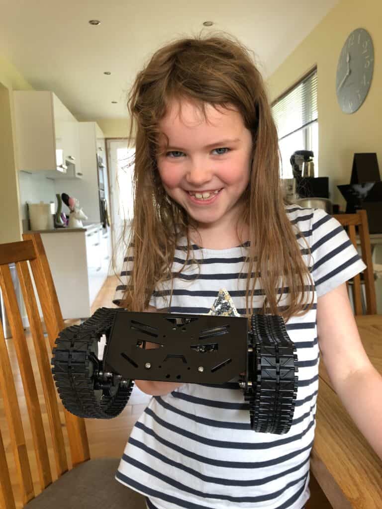
Does it work yet?
Raspberry Pi
In the video series, Chris uses a Raspberry Pi Zero W. The Pi Zero W I had didn’t have the GPIO pins attached, so wasn’t any use for this project, and there were none to be found in stock anywhere, at least not for a sensible price. So I thought I’d try to use the Raspberry Pi 1B I’d had sat in the garage since 2012 gathering dust. Other than being a little too big, and taking quite a while to boot up, it worked fine at the start of the project. It was replace with a Pi 3A+ at the point I started tidying things up, and I now have a Pi Zero W with the GPIO pins if I wanted to use that, but for the time being it’s still running on the 3A+
Motor Controller
The motor controller is the exact same model from the video series and the same one used in the earlier Zumo robot project which is where the idea of using my old Pi 1B came from (that’s what he used back in 2014!). It seems quite a popular device for this type of projects and has worked pretty well. The only thing I’ve struggled with is powering the Pi through the L298N H-Bridge Motor Controller but more on that in the Power section below.
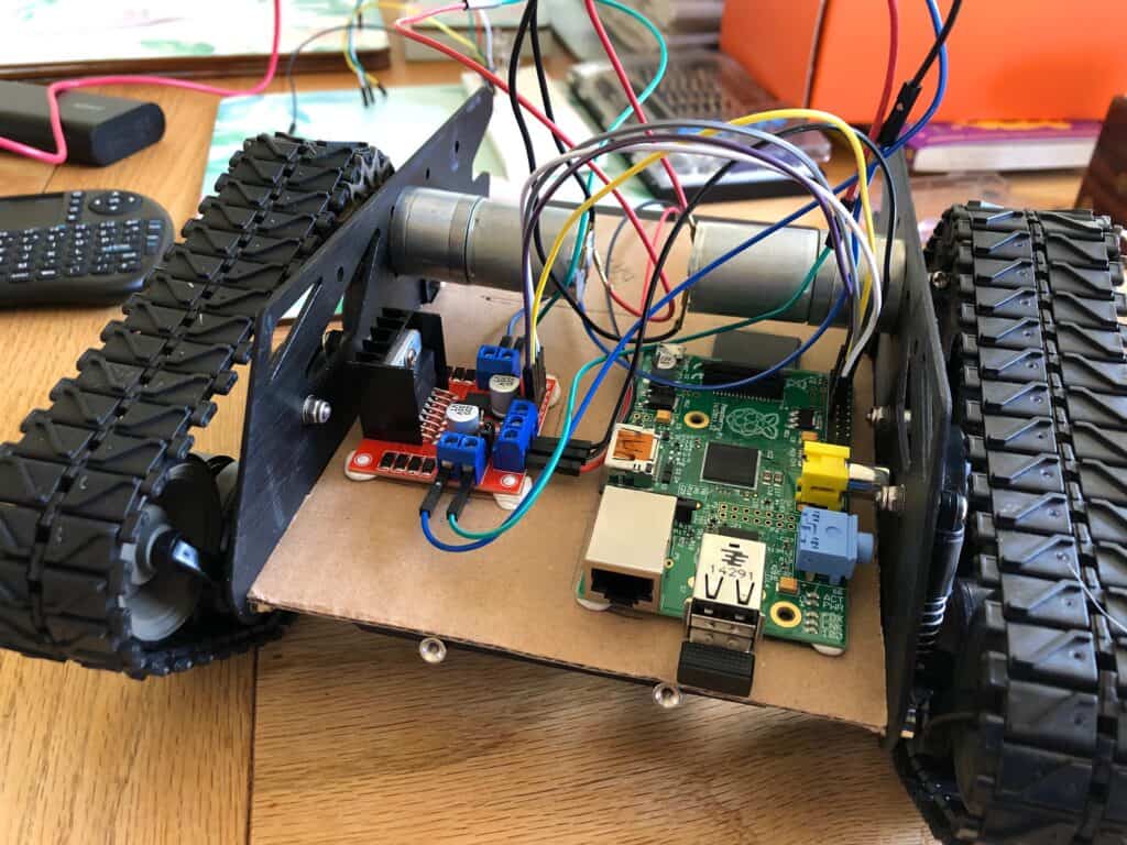
Pi 1B and L298N stuck on some cardboard in the early phases
Code
The code is pretty much stolen from this original Zumo project, and we’ve even added the ‘dance’ routine Chris used to test the robot into our code assigned to Shift-D! Some of the GPIO numbers are different as we clearly have the positive and negative motor connections the other way around, but we’ve not done anything clever at all. I’d really like to play around with the Arduino kit I bought or even try and link to Scratch as my daughter is getting quite good with that now, and could possibly make the robot move using that instead of the keyboard controller. Another project (and blog) for the summer holidays.
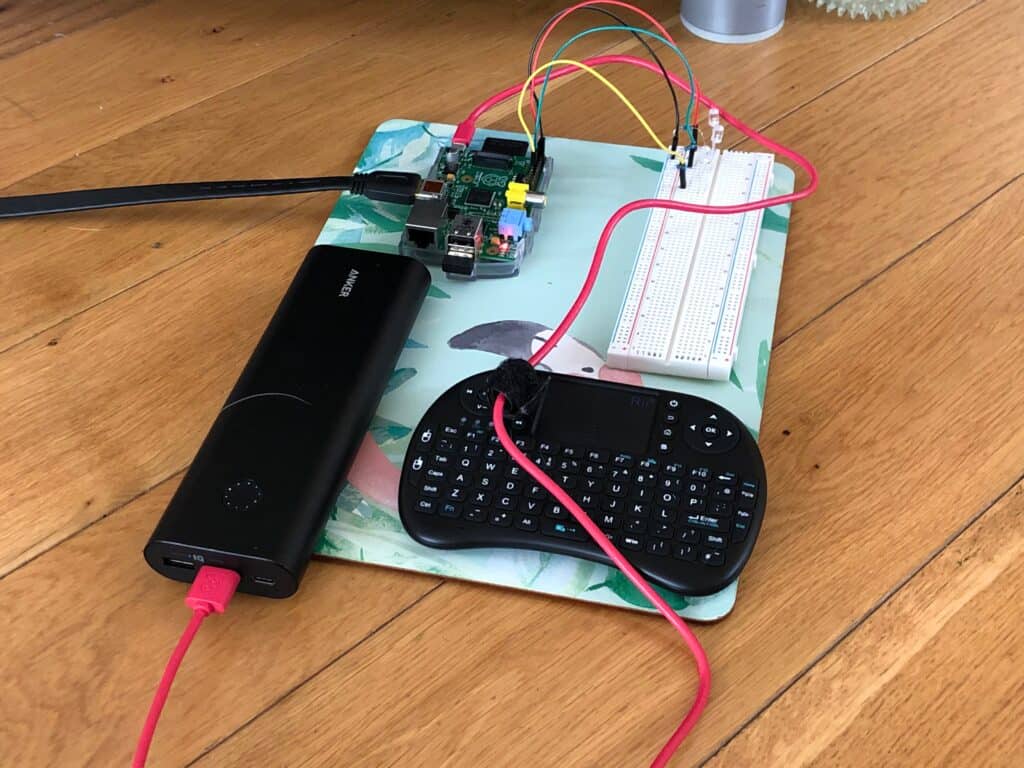
Some of the code was tested on a breadboard (oh, add that to the list of purchases!)
Wiring
I’d bought lots of short wires to use in electronic projects, with male-male, male-female and female-female connectors as I thought these would be useful for other things, and I could just connect them together if I needed longer wires. I think this resulted in some pretty bad wiring, to begin with, and even though it all worked, it was a complete mess and things were badly soldered and taped together. I eventually bought some better ways to connect the wires, some heat-shrink sleeves to remove the tape, and a better soldering iron so I could continue to badly solder things together! I might have been better with some rolls of wire I could cut to the desired length but my soldering did get a little better and was mostly hidden by the plastic sleeves so now looks OK, although I’m sure it wouldn’t stand up to much punishment if someone removes the top cover overly aggressively.
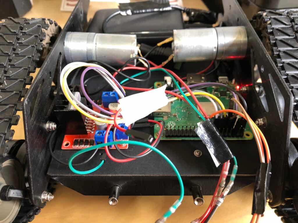
This doesn’t look that messy, but trust me, it was! 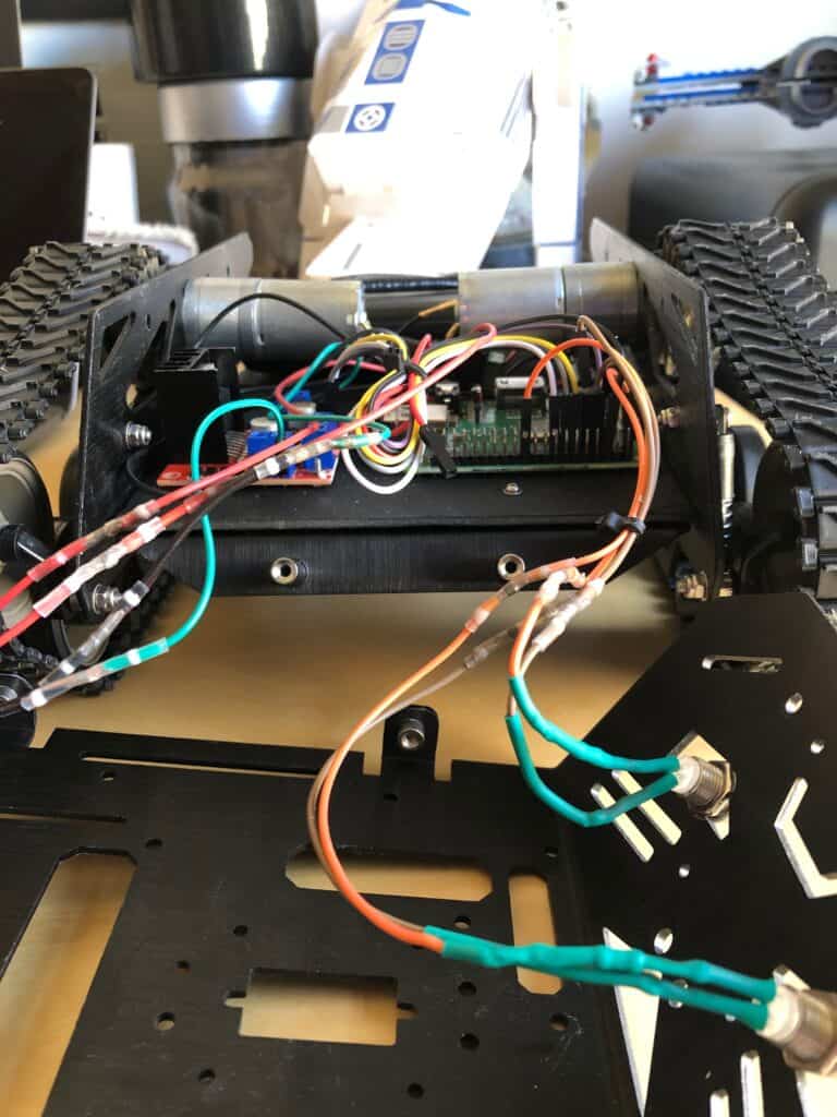
Much neater and all nicely insulated
Power
In the Explaining Computers video series, they’d initially used two separate power sources – the 6×1.5v AA battery pack (that came with the Devastator) for the robot motors and a small rechargeable power bank for the Pi. In later videos they powered the Pi from the L298N controller just using the 9v battery pack, although later struggled to power a camera added to the Pi, so went back to using the power bank. I had no plans to add a camera, so thought the battery pack would do the job for both, and wired things like this from the start, but I think the Pi 1B draws much more power than a Zero W so just couldn’t get it to work – the Pi simply rebooted on start-up
Even when I switched to the Pi 3A+, I had the same problem, so decided to go down a single power bank route. I got a slightly bigger one than used in the videos (but smaller than the one I tested with, which I use to power my Macbook when required) and needed an adapter to convert the power from the USB plug to power the L298N controller. I also played around with the connectors and shorted the wiring so it all fit neatly in the back of the Devastator. It’s still covered in Duck Tape at the minute, which I really need to fix with some heat-shrink sleeves now I have them, but works pretty well and powers both the Pi and L298N .
The final power solution
Lights and Switches
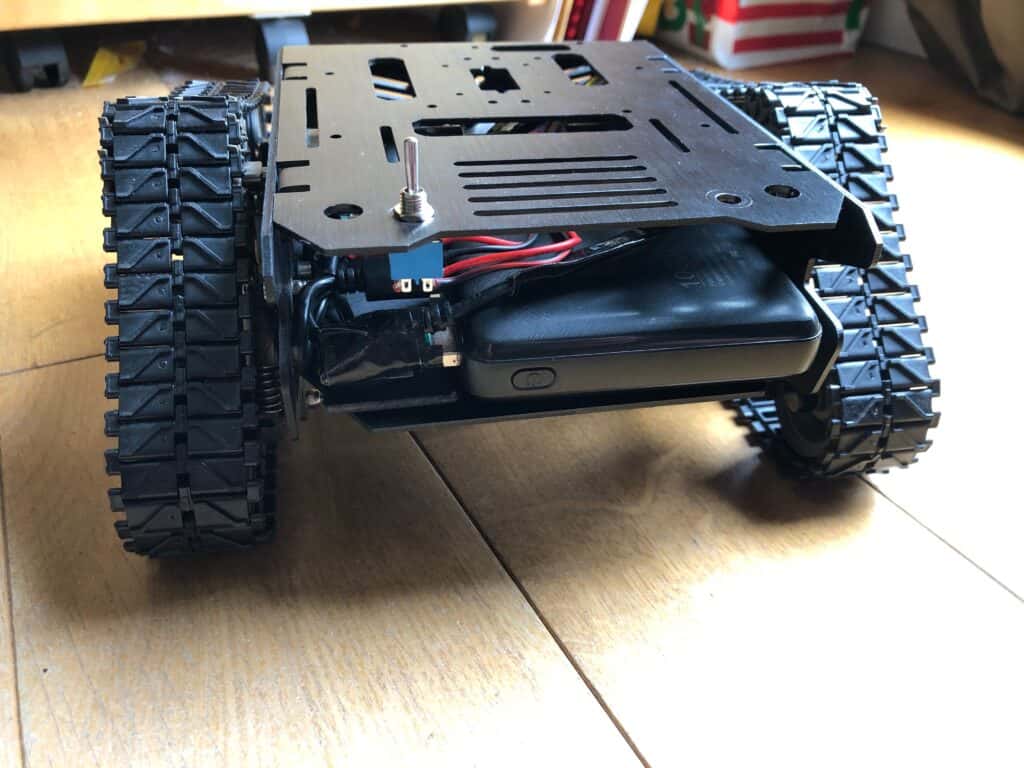
I still have a single switch on the top which is inline between the motors and the controller, so I can switch this on once the Pi had booted and reset the GPIO pins. If it’s left on when powering-up, one of the motors will usually spin, but only one! I went with a similar light configuration, with one confirming power to the Pi and the other which flashes when the Python code is run. My daughter wanted ‘blue eyes’ though, so it looks a little different.
2 switches when I was still trying to use 2 power supplies 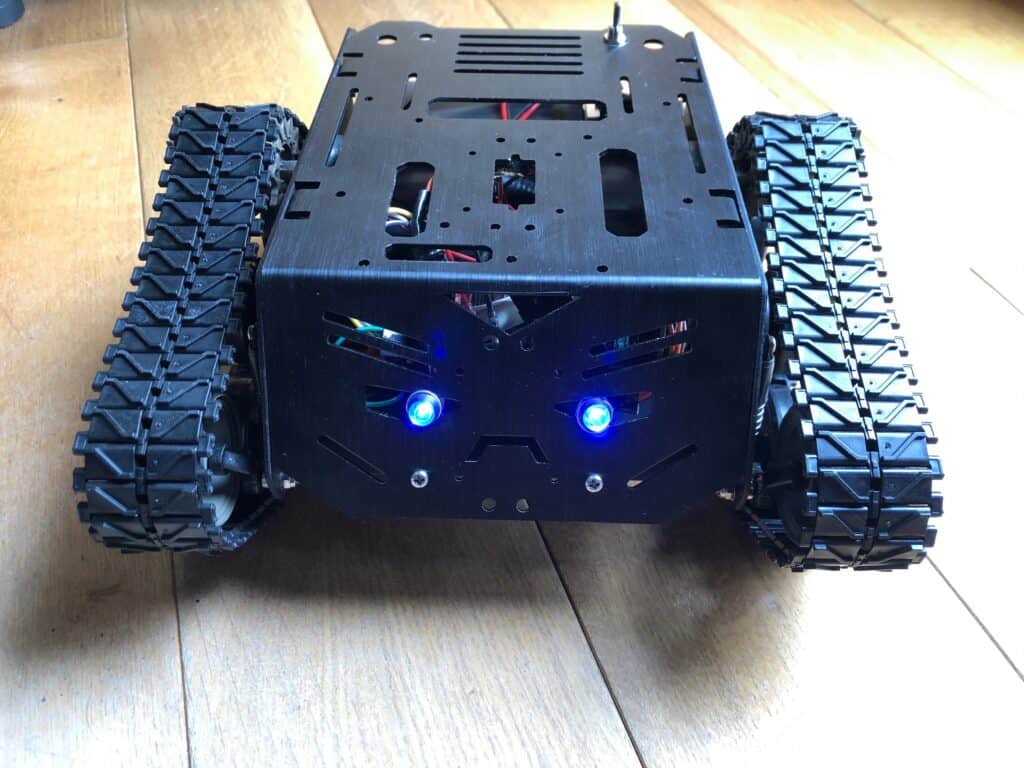
Close to the end, although the switched moved sides
So that’s about it. I’ve taken a couple of videos and some pictures, although they were taken closer to the finish so don’t show too much of my shoddy workmanship near the start. My daughter lost a little interest while I was tinkering with the wiring and power, as ‘she couldn’t see any difference’! I think that was the bit I enjoyed the most, and I’ll certainly be looking at way to develop our Devastator platform and use some of the stuff I bought along the way. It’s hard buying a switch and a couple of LEDs, so I’ve ended up with a reasonable electronics stash for further projects, which should also make them a little cheaper than this one turned out. Good job we’re still pretty much in lockdown and not really spending much money other than food and drink.
Take care and stay safe.
Trackbacks/Pingbacks